Power over Ethernet (PoE), defined by the IEEE 802.3at specification, is a method of securely transmitting application data and power over a CAT-5 Ethernet cable. It is widely used because it supports the flexibility to install equipment anywhere, without the limitations of providing AC power nearby, and without the need for an electrician to install it. The original IEEE 802.3af PoE specification limited the power to the powered device (PD) to only 13W, which limits the range of applications such as IP phones and basic security cameras. In 2009, the IEEE 802.3at specification increased the supported power to 25.5W. However, this is still not enough for PoE applications with ever-increasing power requirements, such as picocell base stations, wireless access points, LED signage, and heated pan/tilt zoom (PTZ) outdoor cameras. In 2011, Linear Technology released a new proprietary standard, LTPoE++TM, which extends the PoE and PoE+ specifications to 90W while maintaining 100% compatibility with the IEEE PoE standard. It supports four different power levels (38.7W, 52.7W, 70W, 90W) and can be adjusted for power supply based on application requirements.
The LTPoE++ Powered Device (PSE) uses a smarter PSE isolation architecture to reduce component count and minimize the use of expensive external components. Comprehensive cable discharge protection and an 80V absolute maximum pin ensure high reliability in field operation. The use of external FETs enables thermal performance to meet application requirements, increasing system efficiency and enhancing long-term reliability. The LTPoE++ architecture requires only one PSE and PD controller to deliver 90W from a pair of 100m CAT-5e cables.
System isolation requirements
To achieve Power over Ethernet, careful selection of architecture and components is required to reduce system cost while improving performance and reliability. A successful design must meet IEEE isolation requirements to protect Hot SwapTM FETs during short-circuit and overcurrent events, or to comply with IEEE specifications. The PoE specification clearly states the isolation requirements, ensuring that the ground loop is broken, maintaining Ethernet data integrity and reducing noise in the PD application circuit.
The traditional PSE isolation architecture isolates the digital interface and power at the host-to-PSE controller interface. Digital isolation units such as optocouplers are inherently very expensive and unreliable. ICs that can achieve isolation are very costly and do not support I2C high-speed transfers. Moreover, isolated DC/DC converters that power PSE logic increase board area and system cost.
Easy isolation
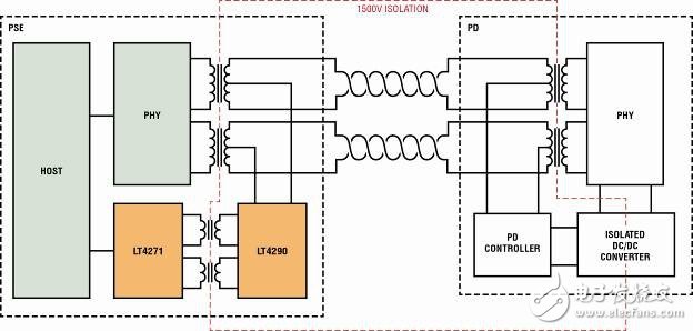
Linear Technology's 12-port (LTC4270 / LTC4271) and 8-port PSE (LTC4290 / LTC4271) chipsets use different PSE isolation methods to migrate all digital functions to the host side of the isolated boundary (Figure 1). This greatly reduces the cost and complexity of the required components. A separate isolated DC/DC power supply is no longer required; the LTC4271 digital controller can use the host's logic power supply. The LTC4271 uses a transformer isolated communication method to control the LTC4290 or LTC4270. Low cost and widely used Ethernet transformer pairs can replace 6 optocouplers. Programming in the protocol implements an I2C communication mechanism with port management, reset, and fast port shutdown to reduce radiant energy and provide 1500V isolation.

Figure 1: The LTC4290 / LTC4271 chipset implements isolation, eliminating the need for any opto-isolators and dedicated isolated DC/DC converters
Reliable cable discharge protection
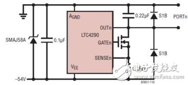
It is important to consider the reliability of your PoE design, especially when dealing with large amounts of cables, high voltages, high currents, or high temperatures. Linear Technology has extensive experience in this area, designed a low-cost, high-throughput circuit protection solution that can flexibly adjust to meet the IEC61000 cable discharge voltage requirements. Only one TVS is needed to protect the high voltage analog supply, and a pair of low cost clamping diodes are used on each of the output ports (Figure 2). The diodes on the port direct unwanted surges into the power rail, which are absorbed by the surge suppressor and the VEE bypass capacitor. Surge suppressors also have the advantage of protecting the PSE controller from VEE supply transients. Linear Technology's PSE controllers also have an 80V absolute maximum rating on all analog pins for transient protection.

Figure 2: Reliable cable discharge protection
Reduce power consumption
Linear Technology's fourth-generation PSE and PD controllers are fully compliant with the IEEE 802.3at specification, and LTPoE++ power reaches 90W while reducing thermal dissipation by using low RDS(ON) external MOSFETs and 0.25Ω sense resistors. This is important for high-power systems where the cost of thermal design and power loss is very high and is also important for power-constrained applications that require as much work power as possible within the power budget. The PSE and PD controllers with integrated MOSFETs have high RDS(ON) parameters, making it difficult to dissipate heat due to heat dissipation inside the device. Damage to one port can cause damage to the entire chip.
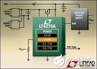
The LT4275 (Figure 3) is the only PD controller on the market that can control external MOSFETs, greatly reducing the total heat dissipation of the PD and improving efficiency, which is important for higher power applications. This innovative approach allows users to adjust the MOSFET to meet the application's thermal and efficiency requirements, supporting the use of low RDS(ON) MOSFETs on the order of 30mΩ. The LT4275 is capable of supporting power up to 90W.
A TVS and 100V absolute maximum port pin is sufficient to protect against cable discharge events. Operating over a wide temperature range of -40°C to 125°C, the LT4275 features over-temperature protection to protect the device from transient overloads. With this more powerful protection, it's easy to experience reliable applications.

Figure 3: LTPoE++ PD Controller Improves Efficiency with External MOSFETs
How does LTPoE++ work?
LTPoE++ uses a 3-event grading mechanism to provide mutual identification between the PSE and the PD while maintaining backward compatibility with the IEEE 802.3at standard. In response to the PD's 3-class grading mechanism, the LTPoE++ PSE determines whether the PD is a Class 1 (PoE), Class 2 (PoE+), or LTPoE++ device. The LTPoE++ PSE uses a 3-event grading mechanism to cause ICUT and ILIM threshold updates. The PSE uses the ICUT threshold to monitor PD current consumption. In the event of a severe current fault, ILIM acts as a hard current limit to protect the PSE supply.
At the other end, the LTPoE++ PD uses the hierarchical event number it receives to determine whether to connect to Class 1, Class 2, or LTPoE++ PSE. If the LTPoE++ PSE measures the first grading event current of the PD to be 0, 1, 2, or 3, the LTPoE++ PSE supplies the port as a Class 1 device. Otherwise, if Level 4 is identified in the first staging event, the LTPoE++ PSE will continue with the second staging event defined by the PoE+ specification. This tells the PD that it is connected to a Class 2 or LTPoE++ PSE. There is no second staging event indicating that the PD is connected to a Class 1 PSE, which is limited to Class 1 power.
The Class 2 PD physical layer hierarchy is defined by the IEEE as two consecutive Level 4 results. An LTPoE++ PD must display two consecutive 4-level results in the first and second hierarchical events, making the LTPoE++ PD appear as a Type 2 PD to a Type 2 PSE.
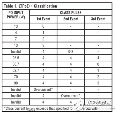
In the first and second grading events, the LTPoE++ PSE migrates to the third grading event after a valid level 4 measurement. After two successful Level 4 measurements, a third grading event was performed. The third grading event must be converted to a different level than level 4, identifying the PD as supporting LTPoE++. During the third grading event, the LTPoE++ PSE considers that the PD that maintains Level 4 is a Class 2 PD. For all grading events, the IEEE 802.3at standard requires compatibility with Class 2 PD Repeat Level 4 responses. The third staging event tells the LTPoE++ PD that it is connected to the LTPoE++ PSE. Table 1 shows the hierarchical event combinations for various PD powers.

LTPoE++ Plug and Play Solution
LTPoE++ provides a secure and reliable plug-and-play solution that greatly reduces the engineering complexity of PSE and PD. The advantage of LTPoE++ over other power extension topologies is that it requires only one PSE and PD to deliver 90W of power on a single CAT-5e cable, saving space, cost, and development time. The LTPoE++ solution reduces material and related component costs and provides the most efficient end-to-end solution today, significantly reducing total cost of ownership, increasing power to practical applications while reducing heat consumption without high The cost of the radiator design.
The most striking thing about LTPoE++ is that it does not require the Link Layer Discovery Protocol (LLDP) developed by the IEEE PoE+ specification for software-level power negotiation. LLDP requires an extension of the standard Ethernet stack and requires significant software development effort. LTPoE++ PSE and PD autonomously negotiate power requirements as well as hardware-level capabilities while maintaining full compatibility with LLDP-based solutions. This way, the LTPoE++ system designer can choose whether or not to implement LLDP. A dedicated end-to-end system may choose to abandon LLDP support. This brings the product to market in a timely manner, but also reduces BOM costs and reduces board area and complexity.
The fourth generation of advanced features
Linear Technology's Power-Ethernet PSE controller family is very mature and professional in PoE experience and is supported by more than 200 million ports. The new fourth-generation features include support for field-updated firmware that will not be outdated in the future. The optional 1-second current averaging is another new feature that simplifies host power management. Advanced power management features include priority fast shutdown, 12-bit per-port voltage and current readback, 8-bit configurable current limit, and 7-bit settable overload current threshold. A 1MHz I2C interface allows the host controller to digitally configure the IC or perform queue port read operations. Provide a “C†library to reduce engineering costs and get products to market as quickly as possible.
in conclusion
Linear Technology offers the industry's lowest power single-port, 4-port, 8-port, and 12-port PSE controllers, as well as rugged ESD and cable discharge protection to reduce component count and cost-effective design. Combined with the LT4275 PD controller, a complete plug-and-play LTPoE++ system delivers 90W while maintaining full compatibility with PoE+ and PoE standards. The entire solution uses an external low RDS(ON) MOSFET to greatly reduce the total heat dissipation of the PD and improve efficiency, which is critical for all power stages. The high value absolute maximum voltage rating and cost-effective cable discharge protection of all analog pins ensure that the device is well protected from the most common Ethernet voltage surges. The LTPoE++ system simplifies power delivery and helps system designers focus their design efforts on high-value applications.
Variable Rf Attenuator,Waveguide Fixed Attenuator,Fixed Attenuator In Microwave,Fixed And Variable Attenuator In Microwave
Chengdu Zysen Technology Co., Ltd. , https://www.zysenmw.com
