Industrial equipment that operates on three-phase AC often requires an auxiliary power stage that provides stable low-voltage DC power for both analog and digital circuits. Examples of such applications include industrial actuators, UPS systems, and energy meters.
The specifications for such power supplies are much more stringent than those required for off-the-shelf standard switches. Not only are the input voltages in these applications higher, but devices designed for three-phase applications in industrial environments must also tolerate very wide fluctuations—including extended drop times, surges, and accidental loss of one or more phases. Moreover, such auxiliary power supplies have a specified input voltage range of 57 VAC to 580 VAC wide.
Designing such a wide range of switching power supplies can be a big challenge, mainly due to the high cost of high voltage MOSFETs and the limitations of the dynamic range of traditional PWM control loops. StackFET technology allows the combination of a less expensive, low-voltage MOSFET rated at 600V and an integrated power controller from Power IntegraTIons, which allows for the design of a switching power supply that is simple and inexpensive and can operate over a wide input voltage range.

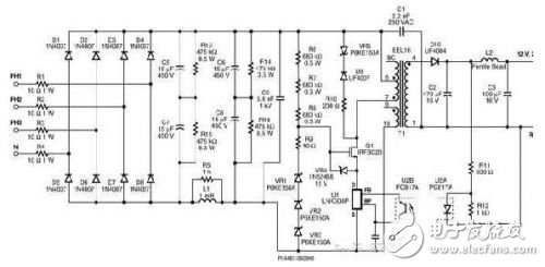
Figure 1: Three-phase input 3W switching power supply using StackFET technology
The circuit works as follows: The input current to the circuit can come from a three-phase three-wire or four-wire system, or even from a single-phase system. The three-phase rectifier consists of diodes D1-D8. Resistors R1-R4 provide inrush current limiting. If a fusible resistor is used, these resistors can be safely disconnected during a fault without the need for a separate fuse. The pi filter consists of C5, C6, C7, C8 and L1, which can filter the rectified DC voltage.
Resistors R13 and R15 are used to balance the voltage between the input filter capacitors.
When the MOSFET in the integrated switch (U1) is turned on, the source of Q1 will be pulled low, R6, R7, and R8 will supply the gate current, and the junction capacitance of VR1 to VR3 will turn on Q1. Zener diode VR4 is used to limit the gate source voltage applied to Q1. When the MOSFET in U1 turns off, the maximum drain voltage of U1 will be clamped by a 450 V clamp network consisting of VR1, VR2 and VR3. This limits the drain voltage of U1 to approximately 450 V.
Any additional voltage at the end of the winding connected to Q1 is applied to Q1. This design effectively distributes the rectified input DC voltage and the total amount of flyback voltage between Q1 and U1. Resistor R9 is used to limit high frequency oscillations during switching, and clamp networks VR5, D9, and R10 are used to limit the peak voltage on the primary due to leakage inductance during the flyback interval.
Output rectification is provided by D1. C2 is the output filter. L2 and C3 form a secondary filter to reduce the switching ripple at the output.
When the output voltage exceeds the total voltage drop of the optocoupler diode and VR6, VR6 will turn on. A change in the output voltage causes a change in the current flowing through the optocoupler diode in U2, which in turn changes the current through the transistor in U2B. When this current exceeds the FB pin threshold current of U1, the next cycle will be suppressed. Output regulation can be achieved by controlling the number of enable and inhibit cycles. Once the switching cycle is turned on, the cycle ends when the current rises to the internal current limit of U1. R11 is used to limit the current flowing through the optocoupler during transient loads and to adjust the gain of the feedback loop. Resistor R12 is used to bias Zener diode VR6.
IC U1 (LNK 304) has a built-in function that protects the circuit from loss of feedback, short-circuit at the output, and overload. Since U1 is powered directly from its drain pin, there is no need to add an additional bias winding to the transformer. C4 is used to provide internal power supply decoupling.
Bubble Bag Machine,Dense Bag Cutting Machine,T-Shirt Bag Cutting Machine,Computer Automatic Bag Cutting Machine
Dongguan Yuantong Technology Co., Ltd. , https://www.ytbagmachine.com
