Abstract: Differential frequency hopping is a digital communication system, which has a fast frequency hopping speed and good communication confidentiality. The receiver uses software radio technology to demodulate. The synchronization of the demodulation window is the key technology and the premise of correct demodulation. The calculation formula of the synchronization algorithm is derived, and the corresponding data chart and flow chart are given. The algorithm has a short synchronous establishment time, a small amount of calculation, and can be adjusted in real time to achieve success in simulation.
1 Introduction to Differential Frequency Hopping
The differential frequency hopping system works in the short wave band (2MHz ~ 30MHz), the frequency hopping speed is 5000 hops / s, and the highest data transmission speed is 19.2kbps. 5000 hops / s frequency jump makes the frequency difficult to track,  Communication confidentiality is good. Differential frequency hopping is different from traditional analog frequency hopping. The transmitter uses DDS to directly synthesize the transmission frequency, and the receiver uses software radio to demodulate.
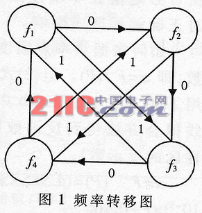
Briefly explain the working mode of the system, see Figure 1 frequency transfer diagram. The data to be sent by the system is 0110110 ... When the first bit '0' arrives, the frequency point is transferred from f1 to f2, and the bit '0' is sent with the frequency f2; when the second bit '1' comes, the frequency point is transferred from f2 to f4. During analogy demodulation, the digital signal sampled from the received signal is subjected to a fast Fourier transform (FFT) operation to identify the current frequency point, and then the frequency transfer diagram and the previous frequency point are demodulated to the original data.
The parameters of the actual system are as follows: the frequency band of 2.56MHz to 28.16MHz is divided into 10 channels at equal intervals, and each channel takes 256 frequency points at equal intervals of 5kHz. Before the communication starts, the system scans 10 channels and dynamically determines a channel with the best characteristics for communication. Both the sending and receiving parties choose 64 as the operating frequency from the 256 frequency points of the selected channel according to the agreement, according to the frequency transfer diagram stored in the system Communicate. The system supports three data transmission rates: 4.8kbps, 9.6kbps and 19.6kbps.
2 Synchronization strategy
Differential frequency hopping systems use software radio methods for data demodulation. The software radio structure reduces the complexity of the system hardware. The receiver does not need the frequency synthesis circuit and hardware synchronization circuit in the traditional analog frequency hopping system. However, after there is no hardware synchronization circuit, which software algorithm to use to quickly achieve synchronization has become one of the key technologies. 
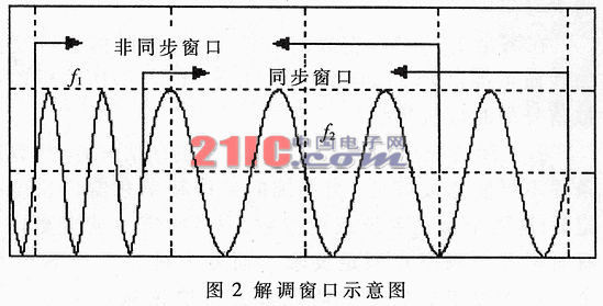
As shown in Figure 2, the received signal is converted into a digital signal after A / D sampling, and then the FFT operation is performed on the sampled data within one hop (hereinafter referred to as the demodulation window) to identify the current frequency point, according to the frequency transfer diagram The original frequency is demodulated at the previous frequency point. If the demodulation window is not synchronized, two frequency points will appear in the window, and it cannot be determined which work should be used as the demodulation frequency point. Therefore, it is necessary to slide the unsynchronized demodulation window to the synchronized position to demodulate the data correctly.
The synchronization method designed by the author is briefly described as follows:
(1) Randomly select the initial window, perform FFT operation on the sampled data, identify the two possible frequency points f1 and f2 and the corresponding amplitudes P1 and P2 after FFT (the energy of the frequency point in the frequency domain is proportional to the square of the amplitude , To simplify the calculation of energy instead of amplitude).
(2) Determine the order of these two frequency points on the time domain waveform.
(3) The amplitude P of the frequency point f (please note that this refers to the frequency-domain amplitude after FFT) is only related to two factors: the time-domain amplitude of the analog signal before sampling and the time of the frequency point in the demodulation window length. The time-domain amplitude of the analog signal can be kept constant at the receiving end by automatic gain control. Then, as long as the frequency point is within the demodulation window, it is a single-valued function according to the length of time (that is, the number of sampling points occupied by the frequency point). The length of the window occupied by the frequency point, and finally slide the window to the appropriate length to synchronize.
The following assumptions: the sampling frequency is fs, the total length of the demodulation window is N, and the length occupied by a certain frequency point is N1.
Definition: α = N1 / N
3 Ways to achieve
The specific implementation needs to consider many complicated situations, detailed description is as follows.
First of all, we must find the functional relationship mentioned in (3), which is denoted as P = F (α).
Under the condition of satisfying (f1 / fs) & TImes; N1 = integer, P = F (α) = A · (N / 4) · α can be derived from the nature of discrete Fourier transform, A is the analog signal before A / D sampling Time-domain amplitude.
But the actual situation is more complicated. The above-mentioned (f1fs) & TImes; N1 = integer condition cannot always be satisfied. When the sampling frequency and window length of the system are determined (these two quantities are system-level parameters,  Once determined, it cannot be changed), only a limited number of frequency points meet the requirements. The differential frequency hopping system requires 64 operating frequency points, and they are selected by the sender and receiver from the 512 frequency points of the selected channel according to the agreement, that is to say, 512 frequency points may become the operating frequency point, most of which are not Meet work. If the conditions are not met, then the formula is modified to P = F (α) = H (f, α) · A · (N / 4) · α. The factor H (f, α) depends on the frequency and α. H (f, α) cannot be dynamically adaptively calculated because it depends on α, and α happens to be the variable to be solved. Therefore, the method of directly calculating the sampled data is not preferable.
Another point is that the frequency hopping system is expected to reduce the sensitivity to synchronization, thereby reducing the complexity and the amount of calculation. Therefore, it is hoped that P = F (α) is a nonlinear function to improve the system characteristics.
A method of adding window function correction to the sampled data in advance may be used. This system uses Hamming window, because Hamming window is the simplest window function that meets the requirements, and the functional formula of P = F (α) can be derived theoretically. Hamming window is defined as:
W (n) = 0.5 + 0.5cos [2 (Ï€-N / 2)] n = 0,1,2, ..., N-1 (1)
After derivation, the estimated formula of P = F (α) after windowing is:
P = F (α) = 0.935A · N · {α / 4-sin (2πα) / (8π) + [cos (α) -1] / (8π)} (2)
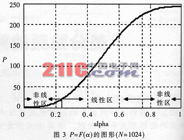
Figure 3 is a graph of P = F (α) obtained by Matlab simulation. The graph is not drawn directly according to formula (2), it is the result of actual simulation, and is independent of formula (2), but the graph of formula (2) is basically this graph. (2) The coefficient 0.93 in the formula can be fine-tuned between (0.92 to 0.94).
Figure 3 is calculated by Matlab according to the following method: corresponding to each value of α, the frequency of 1000 points is randomly selected under the premise of satisfying the sampling theorem, so that the relative length of the window occupied by it is α, and the frequency domain amplitude after FFT is calculated to find 1000 The average value of the points is taken as the ordinate. Therefore, the function expressed in Figure 3 does not depend on the specific frequency. This graph is divided into a linear region and a nonlinear region, and the range of the linear region is 0.25 <α <0.75. When the demodulation window enters the nonlinear region, it means that the window position is very close to the synchronization position, and then it can be synchronized after careful adjustment.
Figure 3 is a nonlinear function as a whole. The benefit of nonlinearity is to reduce the sensitivity of the system to synchronization. Assuming that the demodulation window is slightly out of synchronization, the window must fall in the nonlinear region, where the amplitude change is not significant and will not affect the correct demodulation. 
How to find α according to the frequency point amplitude P? First solve the inverse function of P = F (α), that is α = F-1 (P). But (2) can not find the inverse function of closed analysis. The following methods are available: draw the inverse function of Figure 3 in Matlab, and then use the curve fitting method to obtain the expression of the inverse function (formula (3) is only applicable to the inverse function in the linear region):
α = F-1 (P) = (4.985 & TImes; 10-8) & TImes; P3- (1.8 × 10⁻⁵) × P2 + (4.131 × 10⁻³) × P + 0.166
The second complicated situation is that the demodulation window type must be judged.
Assuming that the initial demodulation window is not synchronized, there are two frequency points f1 and f2 in the window. According to the time domain order of these two frequencies and the length of the occupied window (that is, the amplitude of the two frequencies in the domain), there are four This situation is called type I, II, III, and IV windows respectively, as shown in Figure 4. Each window is assumed to be out of sync and only draws the waveform within one hop.
Why should we determine the window type? Because the frequency point with a larger amplitude is used to solve α in the actual calculation, this can reduce the interference of noise. However, the frequency point with a larger amplitude may be f1 or f2, and the order in the time domain may be in the front or the back, so there are four types of forms.
If the initial window enters the nonlinear region, the amplitude of the frequency point in the nonlinear region changes little. In order to reduce the influence of noise, the point moved in the nonlinear region is a fixed value (this value can be fine-tuned according to actual needs). The criterion for judging whether the window enters the non-linear region is: whether there is a frequency point whose amplitude exceeds the threshold value.
Figure 5
4 Process
After the above discussion, the actual algorithm flow is shown in Figure 5.
Note: If you fail to enter the predetermined synchronization position after sliding the window for the first time, continue the second adjustment. At this time, the moved window enters the large nonlinear region with a high probability. If the second sliding window is still out of sync, the third adjustment is continued. After three adjustments at most, the synchronization lock is entered with a 95% probability. After three adjustments, it is still out of synchronization (at most 5% probability), it is judged as synchronization failure, and the selection window is recalculated.
The above window slides to the right (that is, to slide in the positive direction of the time axis). If the system opens a larger buffer, you can also slide to the left (that is, slide in the negative direction of the time axis). At this time, the previous data cannot be lost. , And the number of sliding points for type III and IV windows becomes a negative value with a smaller absolute value.
The advantage of the synchronization algorithm is that the synchronization establishment time is short, the calculation amount is small, and it can be adjusted in real time. Correcting the window function of the received data reduces the sensitivity of the system to synchronization. The algorithm is successful in system simulation.
Evolis Cleaning Kit,Evolis Primacy Cleaning Kit,Evolis Cleaning Card,Evolis High Trust Cleaning Kit
Miraclean Technology Co., Ltd. , https://www.mrccleanroom.com
