1 Introduction
For the operating system of CI off-machine project
"In the new hump wireless locomotive signal system, the locomotive host is the nerve center of the locomotive equipment. In the automatic control process, data communication and processing are required in real time. It must have multiple communication interfaces, stable platforms, and strong environmental adaptability. This article An ETX-based vehicle computer module design method is proposed. The communication interface is expanded to six serial ports and three CAN ports. It meets the requirements of high and low temperature, humidity, vibration, static electricity and electromagnetic interference in the application.
2 System design
2.1 Hardware composition
ETX (Embedded Technology Extended embedded technology extension) embedded computer module has a complete PC function and efficient CPU performance, providing a perfect solution for embedded applications. In the system design, the main controller is ETX industrial control module, and its core CPU is Celeron 433 CPU. It can provide many common computer interfaces such as VGA, serial port (2), parallel port, IDE, voice, Ethernet port (100M), USB, keyboard, mouse and so on. The product's high-performance peripheral resources and high-quality CPU integrated system greatly facilitate the expansion of peripheral devices and facilitate data exchange between the main CPU and peripheral devices. However, there are more requirements for the communication interface in the new hump wireless locomotive signal system. It is necessary to provide at least 6 serial ports and 3 CAN ports. To this end, the serial port and CAN port need to be expanded. The expansion of the communication interface is completed through the bridge chip and the bus controller. The entire computer adopts the template of European standard 6U standard, and is connected to the backplane through dual 96-core VME.

Figure 1 Block diagram of hardware
2.2 Operating system selection
It is necessary to carry out data communication and processing in real time in the process of automatic control. Therefore, the choice of operating system is very important. For the operating system of the vehicle project, WinCE has better real-time performance, stability and lower power consumption than xp embedded.
As an advanced embedded real-time operating system, WinCE. NET provides rich network and communication standards, an efficient real-time kernel, rich multimedia applications and web functions.
In actual application, it runs under Microsoft WinCE4.2 NET operating system. WinCE4.2 NET is an embedded real-time operating system launched by Microsoft Corporation to meet the stringent real-time requirements of industrial control and other fields. The system has the characteristics of high real-time performance, stable performance and low system resource occupation. At the same time, it has an absolute leading position in the field of embedded multimedia and human-computer interface interaction. Based on the above system characteristics and customer's specific application, the operating system we selected during the design process was WinCE4.2 NET. At the same time, the Winsp system-based bsp package and the corresponding external expansion device WinCE driver are provided for the processing board.
2.3 Environmentally adaptable design
In order to meet the requirements of the vehicle system environment adaptation, the following special work was done in the design:
a) Select industrial-grade devices and components to meet -40 ~ + 70 temperature requirements
b) The whole board is attached with aluminum alloy cold plate to provide good heat dissipation and electromagnetic shielding, and at the same time improve the resistance of the whole board to vibration and impact
c) Three-proof treatment
d) Design an electrostatic discharge circuit to reduce circuit damage caused by static electricity during transportation and installation.
3 Main interface circuit design
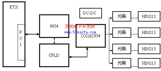
To meet the needs of processing. An important feature of the PCI bus is its extremely high data transmission speed, which is the standard bus for a new generation of microcomputers. The system must solve the conversion problem from PCI to serial port and PCI to CAN port. The functional block diagram of the serial port and CAN port extended from the PCI bus in the functional block diagram is shown in Figure 2.
a) Serial port

Figure 2 4 Block diagram of serial port expansion
The serial port controller used in the schematic diagram is OX16C954, which can expand 4 serial ports (in this system, defined as COM3 to COM6), the data bit can be 5/6/7/8/9, the stop bit can be 1 / 1.5 / 2, each channel has 128 BYTE depth FIFO, and the baud rate can be selected from 50 to 1MB according to the selected clock frequency, both interrupt and query. The performance of the optocoupler is an isolation voltage of 1500V and a transmission rate of 10MB. Drive the bus through HIN213. Among them, COM6 uses a separate isolated power supply, RS232 working mode, and provides all 9-pin functions; COM3, 4, 5 and COM2 on ETX share the same power supply, and provide RS232 and RS485 hardware switching.
b) CAN port

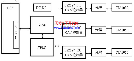
Figure 3 3CAN port expansion principle block diagram
The expansion of CAN port is shown as in Fig. 3. Using Intel's CAN controller I82527. The chip supports CAN 2.0 A / B specification, the baud rate can reach 1MB / S, and I82527 can also provide 16 I / O ports as other controls. The optical isolation device uses HCPL0661, the isolation voltage is 1000V, and the transmission rate is 10MB. The CAN bus transceiver adopts TJA1050, which is specially designed for CAN bus driving, and the transmission rate can reach 1MB. In this board, the three-channel CAN is defined as CAN1, CAN2, CAN3, of which CAN3 is isolated from CAN1 and CAN2 power supply.
c) Design of control interface in CPLD
Complex programmable logic device (CPLD) can be applied to almost all gate arrays and digital integrated circuits of various sizes. It is more and more popular with designers due to its convenient programming, high integration, fast speed and low price. . The CPLD used in this design is EPM7128 of ALTERA Corporation. It uses Altera's new generation of integrated EDA tool Quartus II as a development software and Verilog as the hardware description language to design the circuit.
In the circuits shown in Figures 2 and 3, CPLD devices are used, which makes the design of the hardware circuit very simple. Mainly realize the following functions:
1) Address decoding part
2) Latching of address data
3) Read and write control section
4) Interrupt management part
5) The register part is the interrupt flag and interrupt enable register.
6) LED light control part
The interrupt management part realizes the interrupt of serial port controller and 3 CAN controllers and 8-channel IO interrupt.
This design reconstructs the structure and working mode of its device through software programming, which can be adjusted at any time to meet product upgrades. The hardware design can be as convenient and fast as the software design, thereby changing the design method, design process and design concept of the traditional digital system and the digital system composed of single-chip microcomputer, so that the technical operation and system composition of the system design have become qualitatively Leap.
d) Other function expansion
In order to meet the needs of users, lead 10 leads from the CPLD to the panel LED for programming and demanding. In addition, the CPLD can also provide several I / O ports as other functions.
4 Driver design under Windows
In the process of hardware debugging, debugging is performed under the windows operating system, and the device driver is developed with WinDriver.
a) After opening the WinDriver application, the Driver Wizard appears, select to create a new Diver, a list of all hardware cards in the current system appears, select the hardware device PLX PCI9054 from which the driver needs to be created, and click the Generate.INF File button to create the installation information file , And then modify it according to the information required by the board.
b) Use Driver Wizard to generate application programs and API functions for operating hardware.
c) Start VC ++ 6.0, create a project, include part of the unit files generated by Wizard into the project, and add code to complete specific tasks on this basis.
The startup interface of the test software is shown in Figure 4. 
Figure 4 Test software startup interface
5 Conclusion
cI / O ports.some CAN port, se PCI Bus to extend four seria. As shown so far, the computer module based on this solution has been successfully applied to the locomotive remote control system.
The author of this article is innovative: the module uses the PCI bus to increase the speed, and adopts photoelectric isolation measures for each serial port and CAN, so as to achieve electrical insulation between the system and external devices, design an electrostatic discharge circuit, and reduce the number of transportation and installation processes. Circuit damage caused by static electricity. The whole plate is attached with aluminum alloy cold plate to provide good heat dissipation and electromagnetic shielding, and at the same time improve the vibration resistance and impact resistance of the whole plate.
Custom Equipment Control Cable,Custom Equipment Cable,Equipment Cable,Cable Control
Dong guan Sum Wai Electronic Co,. Ltd. , https://www.sw-cables.com
