The implementation of the Western Development Strategy has enabled Tibet's tourism industry to achieve unprecedented development. However, tourism in Tibet started late, making the current scale and level of tourism development unable to meet the needs of rapid tourism development. At present, there are no tour guides in Tibet, and there are no special tour guides. This has led non-native tour guides to not really grasp the geographical and cultural knowledge of Tibet. The content of the explanation deviates from the original cultural connotation, causing misunderstandings of tourists and unable to fully publicize and promote Tibet. The culture of the nation; the existing small language tour guides can not meet the vast tourist market in Tibet, restricting the development of tourism in Tibet, resulting in the loss of a large number of foreign tourists.
In response to the above problems, in order to promote the development of tourism in Tibet and accelerate the pace of tourism informationization, a solution for the English and Chinese bilingual MP3 tour guide system is proposed here. The tour guide system can locate the visitor's location, and explain the current scenic spot knowledge to the tourists in English and Chinese. In the absence of a tour guide, it can timely and intuitively reflect the current state of the scenic spot, making the travel of the tourists more free and convenient, and enhancing the travel pleasure of the tourists. .
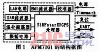
1 APM7101 Features and Protocol Format The APM7101 is a high-performance GPS (Global Positioning System) signal receiver that is small enough to be easily embedded in portable devices. The APM7101 (shown in Figure 1) integrates a SiRFstarIIIGPS processor, LNA circuit, SAW filter, oscillation and calibration circuitry, supports UART communication, and built-in 4Mb flash memory. The device has the following features: 1) 20 channels for reception; 2) fast TTFFs for weak signals (Time to First Fix); 3) 2 UART transceiver channels; 4) receiving sensitivity up to -159 dBm; 5) support for NMEA- 0183 and SiRF protocols; 6) support for SBAS (WAAS, EGONS).
This article refers to the address: http://
After the GPS starts, it will return the received information once every time. The return information includes: GGA(1 s)/GSA(1 s)/RMC(1 s)/GSV(5 s), usually only the RMC information is used. The GPS module of the APM7101 sends messages in the NMEA protocol format. The basic NMEA instruction is an ASCII string that begins with the '$' character to
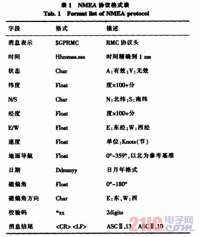
The following example analyzes the NMEA message format:
$GPRMC,161229.487,A,3723.2475,N,12158.3416,W,0.13,309.62,120598,,*10
From the above message, it can be obtained that for the message $GPRMC, 161229.487 indicates that the time is 16:12:29.487 seconds; A indicates that the message is valid; 3723.2475 and N indicate north latitude, 3723.2475; 12158.3416 And E means east longitude, 12158.3416.
2 system hardware overall design according to the needs of each function, its hardware composition block diagram shown in Figure 2, it is mainly composed of SPCE061A microcontroller, GPS module (APM7101), LCD module and voice resource storage module. Among them, APM 7101 is used as the GPS module, SPCE061A is used as the main controller, and the satellite message sent by the GPS module is received through the serial port. The NMEA protocol format is used to analyze it, and the UART is used between the UART and the SPCE061A main control board. Communication, thus achieving positioning function; LCD adopts SPLC501 liquid crystal display module, directly controls display related information through SPCE061A; voice resource storage module adopts SPR4096 module, used for storing information resources of scenic spots, using SPCE061A D/A conversion channel, The audio amplifier circuit composed of SPY0030 is directly output.
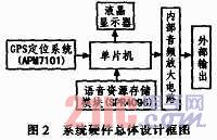
The normal operating voltage of the MCU in Figure 2 is 5 V, and the voltage of its I/O interface is 5 V or 3.3 V. It should be noted that the voltage used by each module is different, and the voltage of the GPS module is generally 3.3 V. The voltage requirement of SPR4096 and LCD module is 5 V. Therefore, the SPR4096 module, the liquid crystal module and the single-chip microcomputer are powered by the same power supply, and the GPS port is used for 3.3 V.
3 GPS global positioning system Figure 3 shows the system block diagram of GPS global positioning system, using SPCE061A microcontroller as the main controller, using UART to communicate with SPCE061A, receiving satellite messages sent by GPS module through serial port, in order to ensure GPS module The sent message is received in time, and the UART adopts the interrupt receiving mode. It is parsed according to the specific format of the message, and finally the parsed information is used for various display and broadcast. The GPS transmits the message in the NMEA protocol format, receives the GPS satellite transmission signal, obtains the necessary positioning information, and completes the positioning work through data processing.

It should be noted here that the power supply voltage of the GPS module should not exceed the given value (3-6.5 V), and the power supply should be 3.3 V, and the polarity of the power supply should not be reversed. Its full-power mode has a current of 68 mA and 1 mA in standby mode.
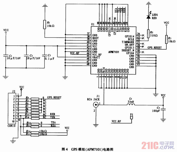
The GPS module uses APM7101 with a positioning accuracy of less than 1Om. The GPS module circuit is shown in Figure 4. After starting, the GPS signal light, that is, the LED in Figure 4 will flash periodically. The UART channel A, B is strobed by selecting a resistor, which defaults to channel A. Similarly, the reset pin is also gated by selecting a resistor, which defaults to the second pin of the interface.
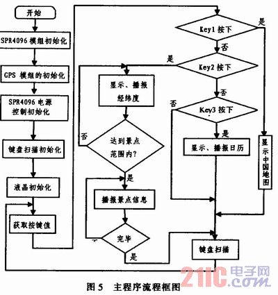
4 System software design The main program is a closed loop. The I/O port initialization part mainly sets the state of the I/O port according to the hardware resource allocation, including the I/O port status, and sets the pull-up resistor, etc., all of which are completed in the I/O port initialization sub-function; GPS initialization is Initialize each hardware module; liquid crystal initialization is mainly to set the relevant data line of the liquid crystal display part and the state of the control line; SPR4096 initialization mainly sets the serial transmission rate and the CPU clock frequency and the corresponding I/O port status. Then the program enters the main loop, and the button scan is continuously performed, and the corresponding function module is entered according to the button value. The main program flow chart is shown in Figure 5.
5 Conclusion When the system works in the normal discharge mode, test the main control board consumption current (the main control board working voltage is DC 5 V), the current consumed by the internal voice amplifier circuit and the GPS (APM7 101) module during the voice broadcast (normal operation) The current consumed by the voltage is 3.3 V DC). The final test results: the main control board consumes 94 mA; the system consumes 80 mA during voice playback; the GPS (APM7101) module consumes 47 mA. The circuit can work stably under the power supply of 5~7 V DC, the system response speed is fast, the voice adopts SPY0030 as the first-stage amplification, the noise filtering effect is good, and the final output tone and sound quality can meet the actual needs. The system can accurately report local latitude and longitude, standard time and details of the attraction. This system will provide a better solution for solving the shortage of guides in Tibet, speeding up the informationization of tourism in Tibet and promoting the development of tourism. It has certain market prospects.
A business tablet must have powerful business functions. At present, users use tablet products more for entertainment, and insufficient development of commercial value has become a major factor restricting the development of tablet computers. Many far-sighted terminal manufacturers have set their sights on the business tablet field.
Generally speaking, when business users choose tablet PC products, they still focus on "regular items" such as processor, battery, operating system, and built-in applications, especially office software applications, which are a good helper for business users.
First of all, there must be powerful office software such as customer management software, which can record customer data and related information anytime, anywhere. There is also a need for powerful marketing software, software marketing, reducing manual intervention, and one person can handle all the publicity and customer information.
Business Tablet,4k Tablet,5G Tablet
Jingjiang Gisen Technology Co.,Ltd , https://www.gisentech.com
