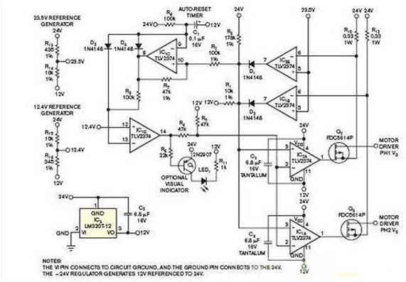
Most circuits are ground-referenced, and components with lower voltages can monitor the low-voltage side of the load, but not the high-voltage side. For example, almost any low-voltage rail-to-rail input op amp can detect boost, which indicates that an overcurrent has passed through the resistor that connects the load to ground. In order to perform the same operation on the high voltage side, a differential amplifier that can withstand a higher common mode voltage is generally selected. This approach limits the choice of input amplifier and raises a question – how to respond to overcurrent? A differential amplifier produces a ground-referenced low signal from a high-side event, but one can prevent it from being caused by a short to ground. The high-voltage side overcurrent only needs to turn off the high-side power supply. In fact, the differential amplifier converts the high side signal to the low side range, and then one must convert the response back to the high side range.

For any high side overcurrent protection circuit, a simpler approach is to have the entire circuit referenced to the rail on the high side. These circuits consume almost no power, and small three-terminal linear inverter regulators can easily power them. However, this approach requires an uncommon configuration that uses a negative transformer with the ground pin connected to the rail on the high side and the input connected to the system ground. There are no other connections to the system. All "ground" points of the overcurrent protection circuit are connected to the output pins of the transformer.
The above figure depicts a two-phase stepper motor fast-acting self-reset high-voltage side circuit breaker. The 24V power supply leads to the motor, and the 12V power supply leads to the circuit breaker. The latter is based on 24V. The circuit breaker treats the 24V motor rail as 12V based on its local ground, which is provided by the output of the transformer. Like all negative linear transformers, this circuit requires a 6.8μF tantalum capacitor.
Both R10 and R12 are 0.33Ω1W resistors that provide current sensing for both phases. The high side power flows through the sense resistor and the P-channel MOSFET to the high side input of the H-bridge (not shown), which drives a motor winding. Any phase current can cause the sense voltage to rise to 0.5V, thereby triggering the circuit breaker. The circuit responds by turning off all two MOSFETs. It then waits for 20ms and turns them on again, thereby automatically clearing the momentary short.
Guangzhou Yunge Tianhong Electronic Technology Co., Ltd , https://www.e-cigarettesfactory.com
