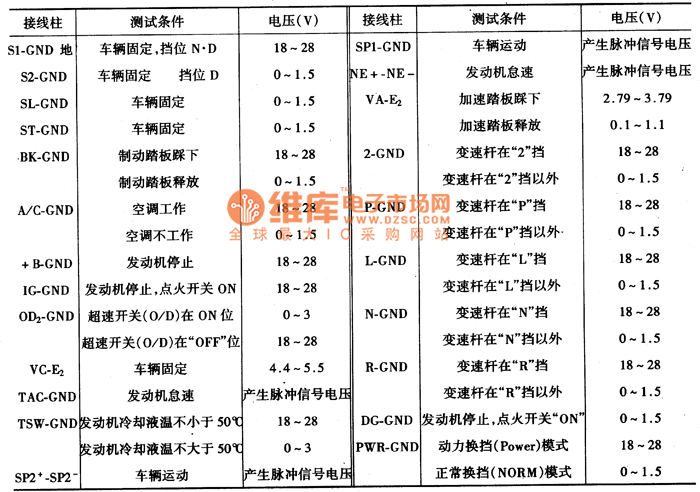
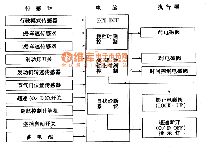
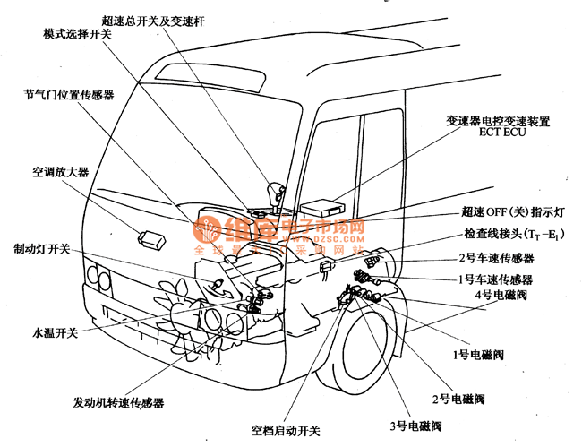
The electronic control system of the A441E automatic transmission consists of a sensor, a computer (electronic control unit ECTECU) and an actuator to control the locking and disengagement of the torque converter. The shifting timing of the planetary gear train is shown in Figure 12. The voltage values ​​of the terminals of the computer ECU under different working conditions are shown in Figure 7.


Automatic transmission electronic control unit (computer) features:
(1) According to the vehicle speed and the throttle position signal, determine the shifting time, and issue commands to the No. 1 shift valve and the No. 2 shift valve to achieve automatic upshift and downshift.
(2) Control overspeed, when the shift lever is in the D position and the overspeed (O/D) switch is turned on, it can be speeded.
If the car is driving in cruise state (CCS), the vehicle speed drops to 40km/h, lower than the set speed, and the overspeed (O/D) switch is in the on state, the ECU of the cruise system (CCS) will give power. The ECTECU sends a signal that the overspeed gear is disengaged and cannot be returned to the overspeed gear until the actual vehicle speed reaches the speed set in the CCS storage.
(3) Control whether the torque converter is locked.
The ECU turns the lock solenoid valve on or off according to the input signals of the vehicle speed sensor and the throttle position sensor, and changes the hydraulic circuit leading to the torque converter through the lock relay valve to engage the lockup clutch of the torque converter or Separation. The lock of the torque converter cannot be performed in the following cases:
1 car brake, when the brake light is on;
2 throttle valve is completely closed, when the throttle idle contact is closed;
3 When the vehicle speed is lower than 4Okm/h or lower than the set speed and the cruise system is working;
4 when the coolant temperature is lower than 70 ° C;
5 When the transmission is upshifting or downshifting.
The automatic shift control assembly check is shown in Figure 8.
The electronic control circuit of the automatic transmission is shown in Figure 14. The terminal position of the computer ECU is shown in the lower part.


switch and socket, Wall switch and socket, push switch and socket
Guangdong Shunde Langzhi Trading CO., Ltd , https://www.langzhielectrical.com
