So far, we have talked about the PS and PL inside the Zynq SOC and the operating system running on the ARM Cortex-A9 processor in the Zynq SoC PS part. But there is one area we haven't explored yet, that is to build a soft core processor on the chip's PL. PicoBlaze is a relatively common soft core in the Xilinx soft core. It is an 8-bit processor, and because of its high accuracy (two cycles per instruction), many Xilinx programmable device-based system designs use PicoBlaze soft core processors instead of state machines and other control structures. You can even use the PicoBlaze processor for serial communication over the I2C and RS232 buses, making the design leaner and saving design time.
The first thing we should do is to download the latest version of the PicoBlaze processor from the PicoBlaze zone. This latest PicoBlaze processor supports all programmable devices in the UltraScale and 7 series (including Zynq SOC).
Our goal is to make it a standard IP module that we can package and add to our VIVADO module diagram. However, before this, our first step is to understand what will happen with the PicoBlaze processor and its development process. In our download directory we will see the following files:
1. KCPSM6.Vhd: This is the source code file for the PicoBlaze processor.
2. KCPSM6.exe: This is the memory required by the assembler to generate machine code and files.
3. ROM_Form.vhd: This is the compiled executable file used to generate the VHDL file, which includes the target program we created.
4. KCPSM6_design_template.vhd: This is an instantiation template file for the PicoBlaze processor.
5. All_kcpsm6_syntax.psm: This file defines all assembly instructions and syntax.
The development process for implementing PicoBlaze on PL is:
1. Write a program to execute the PicoBlaze program. In this example, we will implement a simple water light. We can use the all_KCPSM6_syntax.psm file as a quick reference with the PicoBlaze assembly instructions we will use, and there are a large number of user guides (PDF) in the downloaded files that let us get started quickly.
2. After writing this simple program, we compile with the KCPSM6.exe assembler, which will create a RAM file named with our corresponding program name. This file contains some programs that will be executed by the PicoBlaze controller. You must link this file to the PicoBlaze processor to build the functional system.
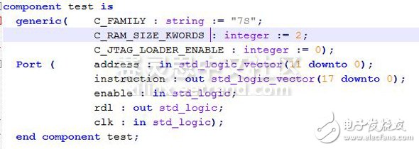
3, modify the RAM file size, as shown below, according to the chip series, 6S changed to 7S, and the memory size is 2K:

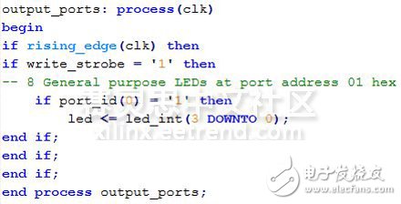
4. In the same folder, create a top-level file to connect the processor and RAM to the other code required by PicoBlaze. For example, when written as follows, declare it as an output port:

5, use VIVADO tools -> "Build and package IP" option to create a new IP, package the above three files into an IP.
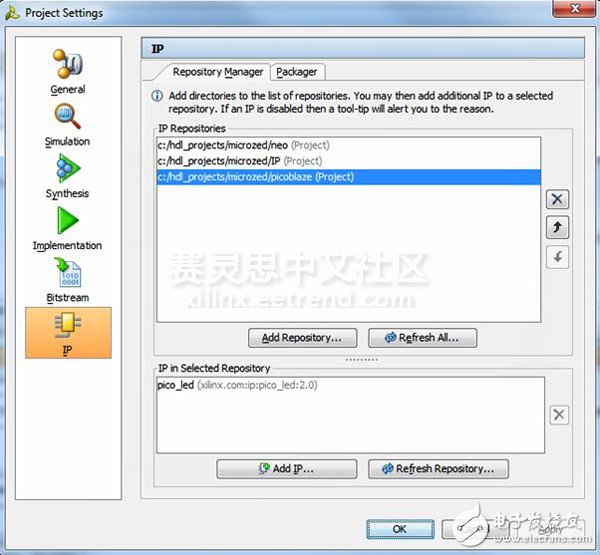
6. After packaging this program, we check to see if it is included as a repository (if not, I will add it manually) and add this IP module to the module diagram.

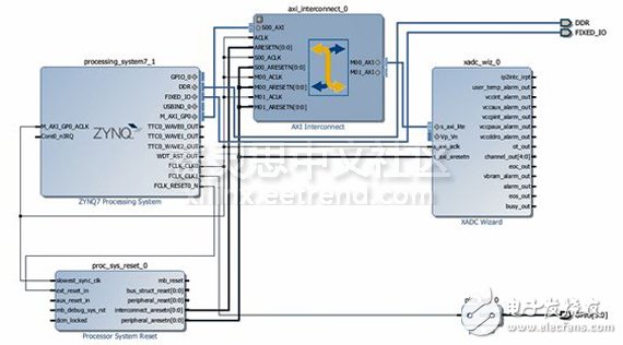
7. Link the clock of the PicoBlaze module to the FPGA clock (set to 40 MHz) and define three output connectors to connect to the IO of the MicroZed LED.
8. Compile the design and export to the SDK

When we compile this design, if we have a JTAG connector, we burn the bitstream file to the FPGA and see if the LED is flashing, or we can export to the SDK and create a Boot file, after booting through Boot File to run this program.
I will delve into the design we just built next time. At the same time, I also attached the files used in this demo to this blog. I have provided PSM files and top level files. If you downloaded the PicoBlaze soft core, you can use the PicoBlaze assembler to generate a Test.vhd memory file.
ZOOKE provides you with safe and reliable connector products, with 3.81 spacing products providing more possibilities for limited space and creating more value for the research and development and production of terminal products.
3.81 wire to board connectors,3.81 connectors,ZOOKE connectors
Zooke Connectors Co., Ltd. , https://www.zooke.com
